IMS Building Technology
IMS Building Technology en práctica
La tecnología IMS para la construcción está basada en una estructura de concreto prefabricada y reforzada, compuesta por elementos básicos reforzados en concreto del sistema IMS.
PRODUCCIÓN DE ELEMENTOS
La flexibilidad y adaptabilidad de la Tecnología IMS para la Construcción a las condiciones locales es obvia en la organización de la sección de producción de los elementos básicos del sistema IMS. Los moldes de acero - el equipo esencial de producción- son portátiles, los elementos manufacturados pueden ser organizados en plantas permanentes, protegidos de las influencias atmosféricas o en secciones poligonales en el lugar de la construcción u otras locaciones cercanas. Una compañía promedio de construcción ya tiene buena parte del equipo requerido para la producción y ensamblaje de los elementos del sistema IMS. 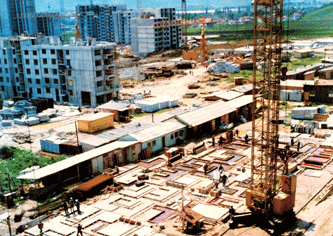
Las plantas permanentes usan grúas de puente apropiadas, plantas de concreto, equipo común para la deposición de concreto (vibradores de concreto, vibradores externos, planchas vibradoras) refuerzan secciones con equipos apropiados para alisar, cortar y rematar así como para ensamblar las hormas, un cuarto de calderas para curación con vapor de los elementos en concreto recién realizados, talleres para el mantenimiento del equipo y el laboratorio de control de calidad del concreto.
La producción en el polígono (aire libre) permite algunas variantes en la organización de la sección dependiendo del clima y otras condiciones; es absolutamente adecuado para plantas permanentes limitadas a un pequeño espacio cerrado; usando grúas de torre en vez de las de puente; el suministro de concreto con mezcladoras de tránsito desde las plantas de concreto; protección del secado directo (en vez de la maduración con vapor) de los elementos recién realizados con láminas de plástico (si las condiciones climáticas lo permiten).
La capacidad de la planta es el factor más significativo para la aplicación racional de la tecnología para construcción IMS. La experiencia muestra que gastos mínimos de inversión en equipo específico para la Tecnología IMS para construcciones se recuperaron por secciones con una producción anual de 20.000 a 50,000 metros cuadrados de estructuras para construcción. En tal caso, la producción anual devaluó definitivamente la inversión en equipos, mientras que el mismo equipo sigue siendo valioso por varios años de producción (8-10 años y más). Las plantas permanentes se construyen, de la misma forma, para 100,000 m2 pero dichas capacidades requieren una organización compleja y un control de construcción, así como un entrenamiento avanzado de los recursos humanos.
El control de calidad del material de construcción y el proceso de producción es necesario para la realización de los elementos así como para la estabilidad y seguridad durante el ensamblaje, levantamiento y utilización.
TRANSPORTE
Para el transporte de los elementos desde la planta de producción hasta el lugar basta utilizar vehículos comunes. Los elementos más pesados no sobrepasan las 7 toneladas, y sus dimensiones permiten el uso de camiones de tráfico público. El radio racional de transporte de un camión es cerca 100km, mientras que en la práctica el de un barco es de cerca 1,000km. Los elementos pueden ser transportados también en tren. 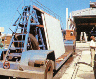
ENSAMBLAJE DEL ARMAZÓN
Cuando los cimientos de la edificación están terminados, con aberturas exactas que se dejan para los anclajes de las columnas prefabricadas, columnas multi-plantas se posicionan y fijan, con la ayuda de abrazaderas, en posición vertical y se controlan con instrumentos de medición geodésica (posiciones verticales y axiales). Los capiteles temporales existen ya en columnas en las cuales la estructura del piso han sido erigidos- las losas de pisos se realizan con monolitos con una red de post-tensión usando cables cortos apropiados. Las uniones entre columnas y las losas de piso se rellenan con un mortero adecuado y luego se dejan endurecer, la totalidad del nivel del piso es post-tensionado con cables en dos direcciones ortogonales. Tras realizar esta acción, las abrazaderas que fijan las columnas se sueltan, los capiteles de soporte se transportan a otro piso y se repite la operación con las losas de piso.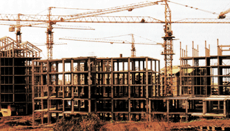
Se utilizan para la construcción grúas y elevadores apropiados disponibles, el número y el rendimiento dependen del tamaño de la construcción y de la locación. Un grupo de 5 a 6 obreros bien organizados y un operador de grúas puede terminar el nivel de un piso de entre 600- 1000 metros cuadrados semanalmente, dependiendo del diseño arquitectónico de la edificación y las condiciones del lugar (facilidades de aproximación de la grúa al lugar, plan de construcción engranado).
Los elementos complementarios de la edificación, fachada, divisiones, trabajos de utilería, pueden colocarse sobre la estructura ensamblada o en niveles superiores aún en progreso, acortan el proceso de construcción y favorecen una muy buena organización y flexibilidad en la construcción de edificios.
La definición de la producción y el proceso de ensamblaje, con normas adecuadas, permite un control adaptado a las condiciones locales, de forma tal que la dinámica de construcción es evidente y los tiempos de entrega se cumplen. La transferencia de la Tecnología IMS para construcción comprende una labor local de entrenamiento en todos los procesos, con una supervisión temporal de expertos del Instituto IMS.
ELEMENTOS BÁSICOS DEL SISTEMA IMS 
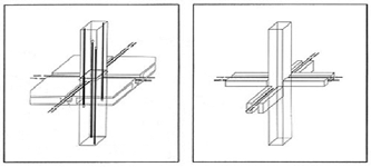
Columnas, continuas a lo largo de máximo 3 niveles (depende de sus secciones de cruce y de la altura de cada nivel o las posibilidades de las grúas utilizadas para la erección), poseen secciones de cruce cuadradas – dimensiones: 30 x 30 – 60 x 60 cm.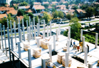
La losa de piso cubre el espacio entre columnas y puede ser manufacturada con o sin techos de concreto, como una única pieza (amplitud de hasta 3.6 x 4.8 m) o multi-piezas con la posibilidad de adaptar sus dimensiones para el transporte y el levantamiento (los techos realizados para unas dimensiones de 9.0 x 9.0 m son construidos a partir de elementos de la más alta calidad);la altura de la viga marginal y de la red de relleno es de 20-40 cm. (dependiendo del largo de las columnas entre las cuales se cubre el espacio), la profundidad del piso de losa entre el artesón es de 4-6 cm., y el del cielo raso es de 3 cm. 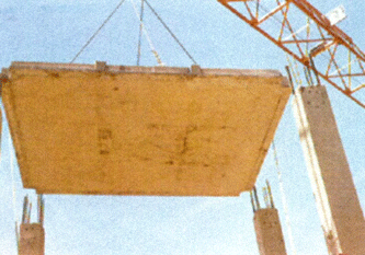
Los modillones de losa de piso, que remplazan las vigas de los bordes en las soluciones arquitectónicas son balcones, logias y otros espacios caseros que pueden prescindir de columnas y los cuales están conectados únicamente por dos columnas (como modillones) y cuya altura y largo corresponden a las losas de piso junto a las cuales fueron realizados, mientras que su ancho máximo está limitado a 1/3 del largo longitudinal. Son rellenados y pueden realizarse con o sin techos de concreto.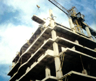
Las vigas de los bordes tienen una posición limítrofe con el fin de formar estructuras con vigas y fachadas de construcción. Sus largos y profundidades son las mismas ya que corresponden a las losas de piso con las cuales forman una estructura con vigas y su ancho se elige de acuerdo con los requerimientos arquitectónicos para el tipo adecuado de muros de fachada.
Los muros reforzados son paneles reforzados de concreto (profundidad mínima – 15cm), los cuales refuerzan la armazón. Están colocados, siguiendo la regla, en los ejes de dos columnas adyacentes, con la función de formar, junto con las columnas, un elemento estructural desde los cimientos hasta el techo, listo para recibir la intensidad de las fuerzas horizontales requeridas (en práctica, dichos elementos por lo general se realizan en concreto en el mismo lugar, especialmente en grandes bóvedas debido a las grandes dimensiones, el peso y el levantamiento lento).
Elevadores para boqueras – en la práctica tales elementos se preparan en sito, dado que son series no racionales (es un número pequeño de elementos en la construcción de una edificación en relación con el precio por molde por manufacturar dentro de la propia sección), los cuales, por regla son capaces de resistir las fuerzas horizontales junto son los muros reforzados. 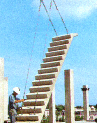
Elementos para escaleras para un nivel, dos niveles o tres niveles de escaleras con escalones prefabricados de monolito.
DESCARGA EL BROCHURE PDF
Inglés (0.8 MB)Español (0.8 MB)
Serbio (0.8 MB)
SÓLO TEXTO
•IMS Building Technology en práctica


 COUNTRY OF ORIGIN